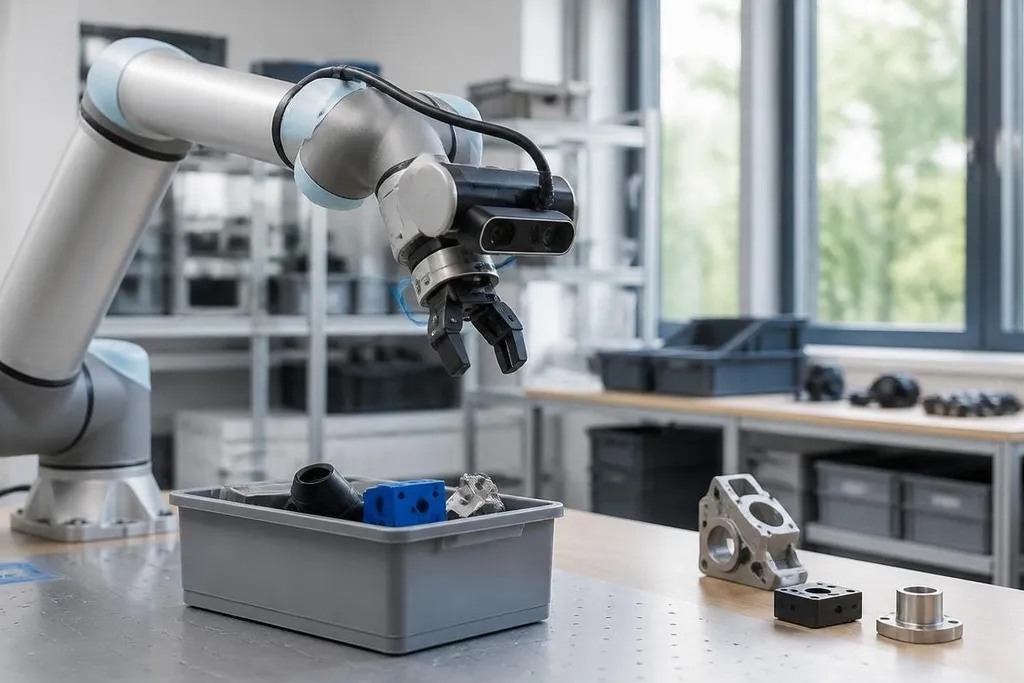
A robot camera turns light into numbers, then software uses those numbers to guide movement. The hard part starts after the picture arrives: the robot must work out where an object is, what it is, and whether it can safely touch it.
- A camera records light as pixels, not objects.
- Stereo cameras estimate depth by comparing two views.
- Good results depend on lighting, calibration, and clear software rules.
Camera data starts as light
A standard camera records color and brightness across a grid of pixels.
Each pixel stores a small piece of the scene, and the full image gives the robot information about edges, shapes, and surface color.
That image still needs meaning. A box on a conveyor may cover only a small part of the frame, while glare can make its top look like a different color. Software checks patterns in the pixels and marks areas that may contain the object.
The lens affects what the robot can use. A wide lens shows more of the work area but can bend lines near the edges. A narrow lens gives a smaller view and may help the robot measure a known station more consistently.
From pixels to objects
Robot vision software usually works in stages. It receives an image, finds useful features, compares those features with a trained model or set of rules, and sends a result to the control system.
That result may be a label such as “box,” a location in the image, or the outline of an object. The robot can then place its gripper near that outline instead of moving to a fixed point every time.
The location in the image is not yet a location in the robot's workspace. Calibration connects the camera's coordinate system to the robot's arm or mobile base. Without that link, the robot may find the right object and still reach the wrong spot.
Calibration gives you a test for camera claims: can the robot place an object at a known point, or can it only spot the object in an image? Robot24.com machine vision coverage adds named robots and tasks to that check. Depth measurement comes next, because a 2D image can show where an object is without showing how far away it sits.
How robots measure depth
A single camera makes a flat image. It cannot directly tell if a small object is close to the lens or a larger object is farther away. Robots get depth from extra sensors or from software that uses movement and known geometry.
A stereo camera has two lenses. The software compares the same feature in each view, then uses the difference between those positions to estimate distance. This works well when the scene has visible edges or texture.
Time-of-flight cameras send out light and measure how long it takes to return. The result is a depth image, where each pixel also carries distance information. These cameras can struggle with shiny, dark, or very bright surfaces, so the room and the object still matter.
A robot can also build depth from motion. As the camera moves, nearby objects shift across the image faster than distant ones. Software can use that change to estimate the robot's position and the shape of nearby surfaces.
Where camera vision fails
Light is the first limit. Shadows, reflections, low light, and direct sunlight can change the image enough to confuse software. Dust on the lens or a loose camera mount can cause a similar problem.
Occlusion creates another gap. If one item covers part of another, the robot may see only a handle, corner, or label. A fixed camera angle makes this worse because the missing section never appears in the image.
Motion also matters. A moving robot or conveyor can blur an image, while a slow camera can leave the software working with an old view. The control system needs to account for the delay between taking the image and moving the arm.
I'd treat camera output as a measurement with limits, not proof that the robot understands the scene. A second view, depth sensor, or physical check may be needed before a fast arm moves near a person.
A practical camera checklist
Before adding cameras to a robot cell, check these points:
- Set the view: Keep the full work area visible, including the places where objects enter and leave.
- Check the light: Test bright, dim, reflective, and shadowed conditions during normal operation.
- Run calibration: Measure the camera-to-robot position after mounting and after any impact or adjustment.
- Test bad views: Cover part of an object, rotate it, and place it near another item.
- Set a safe response: Tell the robot to stop or ask for another image when confidence or depth data falls below the set limit.
These checks connect the camera's image to the robot's real task. A sorting arm needs object location and timing, while an inspection system may need fine detail and steady light.
The next useful step is to test the complete loop: image, decision, robot motion, and result. A camera that identifies a box correctly but sends the arm to the wrong height still leaves the job unfinished.